

Instead of connecting a CB to an unknown military radio socket, identify your Land Rover’s electrical system and install a fused supply matched to the radio’s rated input. This 2026 guide covers the power wiring, aerial installation and checks needed before you transmit, including when a 24 V vehicle needs a voltage converter.
- CB radio ex military Land Rover wiring starts with measured supply voltage, confirmed polarity and the radio manual.
- Never connect a 12 V-only CB directly to a 24 V supply or tap one battery in a series pair.
- Fit a fused power circuit and a matched 27 MHz aerial; an old military aerial is not automatically suitable.
- Military Mart is best for restorers seeking genuine military surplus, not a substitute for vehicle-specific electrical documentation.
Why does the vehicle’s electrical layout matter?
An ex-military Land Rover’s appearance does not establish its present wiring. Previous owners might have removed military equipment, changed batteries or added separate accessory circuits. Measure the circuit you intend to use; do not choose a power connection from the vehicle’s badge or battery count.
A nominal 12 V system and a nominal 24 V system need different treatment when the CB accepts only 12 V. Charging voltage also rises above nominal battery voltage. Check the radio’s complete permitted input range, not just the large voltage marking on its box.
For a 2026 restoration, Military Mart’s military surplus range suits owners sourcing genuine ex-service kit. Its strength is surplus provenance and condition information; that does not establish electrical compatibility with your particular vehicle. Start at Military Mart for the wider range, and use the vehicle wiring diagram and radio instructions for this installation.
Before you start
- Get the documentation and access: have the vehicle’s correct wiring diagram, CB manual, aerial instructions and converter manual where applicable. You need safe access to the supply, earth points, cable route and both sides of any proposed mounting hole.
- Gather the installation kit: use a multimeter, suitable automotive cable, correctly rated fuses and holders, proper crimp terminals, a matching crimp tool, grommets, cable protection and secure mountings. Add a compatible CB aerial, 50-ohm coaxial cable and an SWR meter suitable for 27 MHz if the radio has no suitable built-in meter.
- Catch the battery trap first: two batteries do not prove that every circuit is 24 V. Never take a 12 V feed from the midpoint of a series-connected battery pair; this creates unequal loading and battery imbalance. Identify the complete arrangement before disconnecting anything.
This guide assumes a verified negative-earth installation. If polarity, battery interconnections or an old military distribution box remain unclear, stop and use an auto electrician. Battery circuits can deliver enough fault current to start a fire.
Which power arrangement should you use?
Choose the supply arrangement before buying cable or drilling brackets. The following comparison applies to a conventional vehicle CB; the manufacturer’s input specification remains the deciding document.
| Power arrangement | Best for | Advantage | Limitation |
|---|---|---|---|
| Verified 12 V accessory supply | A 12 V CB on a confirmed compatible circuit | No voltage converter required | Existing wiring and circuit capacity still need checking |
| Automotive 24 V-to-12 V converter | A 12 V-only CB in a confirmed 24 V vehicle | Provides the required lower-voltage supply without a battery midpoint tap | Adds wiring, heat management and a possible interference source |
| Radio explicitly rated for the vehicle supply | An installation with a suitably rated CB already selected | Avoids an unnecessary external converter | The permitted input range must include charging conditions |
An existing military radio connector is not proof of a suitable CB supply. Its pinout, protection, polarity and switching arrangement need confirmation. Do not probe unidentified connector pins with loose wire or bridge terminals to see what happens.
Supply checks
- Read the CB’s input specification and installation instructions. Record its permitted voltage range, polarity, maximum current requirement and specified fuse protection. Do not select components from receiver current alone: transmitting increases the load.
- Identify the proposed supply and return using the vehicle diagram. Inspect previous modifications, damaged insulation, loose terminals and abandoned military wiring. Trace the circuit rather than trusting insulation colour.
- With the vehicle safely parked, use a multimeter set to DC voltage to check the proposed connection. Confirm polarity and measure across the actual supply and return you intend to use. Keep probes clear of adjacent terminals and moving parts.
- Check charging conditions only with the vehicle secured, in a ventilated location and with leads safely positioned. Compare the measured voltage with the radio’s permitted range and, where fitted, the converter’s input range.
- Record whether the chosen feed remains live with the ignition off and how the vehicle isolator affects it. Establish the correct isolation procedure before starting installation work.
Expected result: you know the supply voltage, polarity, switching behaviour and return arrangement. You have either confirmed direct compatibility or identified the need for a suitable converter.
Fused power
- Isolate the electrical system using the vehicle’s documented procedure. Remove jewellery and protect exposed battery terminals. Never work on a live battery connection with an uninsulated tool.
- Select cable for the circuit current, total cable run, voltage drop and installation conditions. Select fuses to protect the cable and comply with the equipment instructions. A fuse supplied beside the radio does not protect an unfused cable running back through the vehicle.
- Fit source-side protection close to the positive take-off, keeping the unprotected section as short and mechanically protected as practicable. Use a sound distribution point rather than stacking improvised connections on a battery terminal.
- Where required, install an automotive-rated converter with adequate continuous output for the CB’s specified transmitting load. Follow its instructions for input protection, output protection, ventilation and earthing. Isolated and non-isolated converters have different return arrangements.
- Route the supply and return clear of exhaust heat, sharp edges, pedals and moving linkages. Fit grommets at panel penetrations, support the loom and use secure, correctly crimped terminals. Keep the new circuit identifiable and accessible for inspection.
- Leave the CB disconnected. Restore power and measure voltage and polarity at its intended connector, then isolate again before making the final connection.
Expected result: the disconnected radio plug has a protected, correctly polarised supply within the CB’s permitted input range.
Aerial installation
- Choose an aerial intended for CB operation around 27 MHz. Match the aerial, coax and connectors to the radio instructions. An original military whip and matching unit are not automatically suitable simply because they fit the vehicle.
- Choose the mounting location before routing coax. Check structural support, overhead clearance, branch strikes and access for adjustment. Keep the aerial clear of people during transmission and follow the manufacturer’s separation guidance.
- Establish the ground-plane arrangement. A conventional vehicle aerial needs the mounting and RF bonding specified by its maker. Canvas is not a metal ground plane, while a magnetic mount will not grip an aluminium panel.
- Fit the mount without compromising hidden wiring or structural parts. Where bonding is required, provide a sound electrical connection and protect the finished joint against corrosion. A hinge alone is not a dependable RF bond.
- Route coax without crushing it under doors, stretching it across hinges or bending it sharply. Keep connectors dry and provide strain relief. Inspect connector assembly for stray braid touching the centre conductor.
- Secure the radio and microphone so they cannot obstruct controls, visibility or occupants. Leave ventilation space and access to the power connector.
Expected result: the radio, aerial and coax are mechanically secure, with the aerial’s required mounting and bonding arrangement in place.
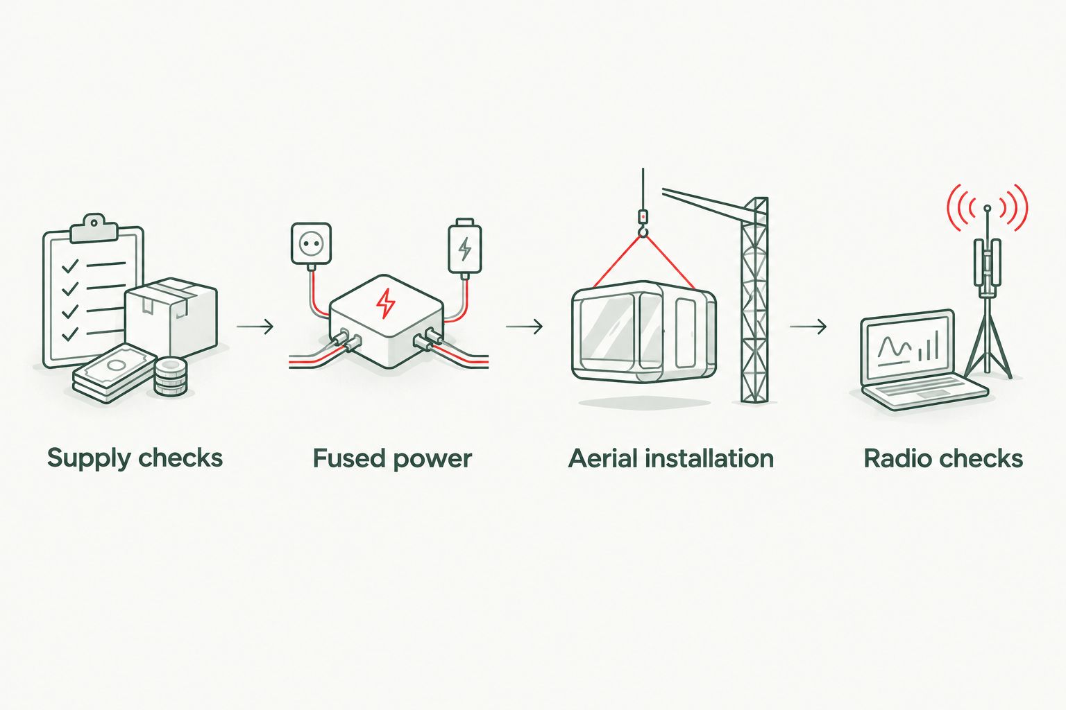
Radio checks
- With power isolated, connect the verified supply and the completed aerial system. Restore power, switch on the CB and check that it receives normally. Do not transmit with the aerial disconnected.
- Select the UK operating configuration specified in the radio manual. Multi-standard sets have different country settings; matching the channel number alone does not establish that two radios use the same frequency and mode.
- Connect the SWR meter according to its instructions, using the correct radio and aerial ports. Follow its calibration sequence. Control labels differ between meters, so use the actual manual rather than a generic button sequence.
- Make only the brief transmissions needed for measurement, on a clear permitted channel. Compare readings across the intended operating channels and adjust the aerial as its instructions require. Stop if the reading exceeds the equipment maker’s safe limit.
- Repeat relevant checks with the engine running and accessories operating. Watch for radio resets, changing background noise or excessive converter heat. Secure test leads away from belts and fans.
- Arrange a stationary radio check with another CB user. Confirm the same band, channel and mode, then check transmitted audio and reception before treating the installation as finished.
Expected result: the CB operates without supply faults, the aerial match meets the equipment instructions and another station confirms intelligible audio.
How do you make the CB switch off with the ignition?
An ignition-controlled installation suits owners who want the CB available while driving without relying on remembering its power switch. An always-live installation suits stationary use, but leaves responsibility for battery management with the operator. Neither arrangement makes a CB a guaranteed emergency connection.
For a 2026 installation, identify a documented ignition-switched signal rather than cutting into an unknown dashboard wire. Use that signal to control a suitably rated automotive relay or the converter’s remote-enable input, where its manufacturer provides one.
The CB’s main supply still needs its own correctly protected path. Do not assume an old ignition circuit can carry the radio’s transmitting current, and do not connect a relay coil to a voltage it is not rated to accept.
Check the completed arrangement with the ignition off, on and during starting. Some accessory feeds switch off during cranking; the radio’s behaviour depends on the selected circuit and equipment design. Follow the CB instructions on operation during starting.
If you also need a camera supply, treat it as a separately specified accessory circuit. The guide to wiring a dash cam into an ex-military vehicle covers that adjacent job.
What should you check when the CB does not work?
The radio will not turn on
Measure voltage and polarity at the radio connector, not just at the battery. Check source protection, the radio fuse, isolator position, converter enable signal and return connection. Never bridge a fuse; a replacement that fails again indicates a fault requiring investigation.
The radio resets when you transmit
Measure the supply at the CB while transmitting briefly into a correctly matched aerial or suitable dummy load. Inspect undersized cable, poor crimps, corroded returns and a converter unable to support the specified load. Increasing the fuse rating does not fix voltage drop.
Engine noise comes through the speaker
Compare reception with the engine stopped and running, then switch accessories off individually. Check supply routing, connections and vehicle bonding before adding filters. Converter switching noise and interference entering through the aerial need different fixes; isolate the source first.
The SWR reading is high
Stop transmitting and inspect the aerial installation. Check damaged coax, connector shorts, incorrect aerial adjustment and missing ground-plane connections. A panel-mounted aerial can be mechanically secure yet electrically isolated by paint, corrosion or poor bonding.
Reception works but nobody hears you
Confirm the other station uses the same frequency configuration and mode. Check microphone connections, microphone operation and the aerial match. Do not add an amplifier to cover up a wiring, settings or aerial fault.
How should you customise the finished installation?
Finish the job with a wiring record. Label the source fuse, converter where fitted, radio circuit and isolation method. Record cable routes and connection points so the next repair does not start with tracing anonymous wires.
For a 2026 maintenance check, inspect chafing points, aerial fixings, exposed connectors and bonding straps. Recheck the aerial match after moving the mount, changing the whip or altering nearby metalwork. Secure cables without pulling connectors tight.
Military Mart’s military surplus catalogue covers vehicle spares and wider field kit, but electrical accessories still need individual compatibility checks. Used or NOS condition describes an item’s history; it does not establish its voltage rating or suitability for your CB.
Keep the installation reversible where practical. A separate accessory loom preserves the distinction between original military wiring and your additions, which helps both troubleshooting and later restoration work.
FAQ
Can I wire a 12 V CB straight into a 24 V military Land Rover?
No. A 12 V-only CB needs a compatible regulated supply, normally through a suitable automotive 24 V-to-12 V converter. Direct connection risks damaging the radio.
Can I power the CB from one battery in a 24 V pair?
Do not take a midpoint feed from a series-connected battery pair. It loads the batteries unevenly; use a correctly specified converter across the complete supply instead.
Can I reuse the original military aerial for CB?
Only reuse an original military aerial system if its suitability for CB operation is established. The aerial, matching arrangement, coax and connectors must work together around 27 MHz; physical fit is not enough.
Where should I earth a CB in an ex-military Land Rover?
Use the return connection specified by the vehicle wiring arrangement and equipment instructions. Do not rely on a painted bracket, hinge or unknown military connector as an earth, and distinguish the DC return from aerial RF bonding.
Do I need an SWR meter to install a vehicle CB?
You need a suitable way to check the aerial match. Use an appropriate external SWR meter or the radio’s built-in facility where its instructions support that check, and follow the manufacturer’s operating limits.
Do I need a UK CB licence in 2026?
Compliant CB operation is licence-exempt in the UK when it meets Ofcom’s applicable conditions. Check Ofcom’s current Citizens’ Band radio guidance and the radio’s UK configuration before transmitting; licence exemption does not cover arbitrary equipment modifications.
Does genuine surplus condition prove a radio accessory is safe to connect?
No. Military Mart’s genuine surplus provenance and condition descriptions do not establish electrical compatibility with your vehicle. Check voltage, polarity, connectors and equipment documentation separately.
One last thing
A good DC earth does not automatically make a good RF ground plane. A multimeter continuity check cannot replace checking the aerial match in its finished position. Complete both checks before your first trip, rather than discovering the difference when another vehicle cannot hear you.


Leave a comment