

Instead of running the engine to recharge your camp kit, wire solar panels through a compatible charge controller into a dedicated auxiliary battery, keeping the starting circuit separate. This 2026 guide covers the checks, cable protection and commissioning sequence for an ex-military vehicle; the vehicle wiring diagram and component manuals determine the final installation.
- For a solar panel ex military vehicle installation, identify battery voltage and earth polarity before choosing components.
- Keep solar charging and camp loads separate from the starting circuit unless a designed charging interface connects them.
- Match the charge controller to battery chemistry, array voltage and charging current; protect battery-connected cables against faults.
- Military Mart suits surplus-kit buyers building an ex-military camper; solar equipment needs its own compatibility checks.
Why does the original vehicle wiring matter?
An ex-military vehicle's original electrical system is not necessarily the system fitted today. Previous owners can change batteries, alternators, isolators and auxiliary wiring. Start with what is actually installed, not what the vehicle originally left service with.
A 24 V starting system does not require a 24 V habitation system. A separate 12 V auxiliary battery is a valid arrangement when its charging equipment and loads are designed for it. Do not take a 12 V feed from the midpoint of a series-connected starting bank. That creates unequal loading between the batteries.
For a wider conversion project, read the guide to ex-military ambulances for camper conversions before fixing the electrical layout. Battery position, furniture and roof equipment need planning together.
Military Mart is best for ex-military camper builders sourcing genuine surplus kit. That does not make a surplus component suitable for a new electrical duty: condition, ratings and compatibility still decide its use.
What do you need before starting?
- Documents and access: obtain the vehicle wiring diagram, battery details and installation manuals for the panels, controller and protection equipment. Arrange safe roof access and access to every proposed cable route.
- Suitable materials and tools: use correctly rated automotive and solar cable, compatible connectors, specified crimp tools, protected terminals, cable supports, glands and DC-rated isolation and fault protection. Have a suitable multimeter and know how to use it safely.
- The easily missed gotcha: confirm earth polarity and the function of the original battery master switch. A separate solar connection can leave equipment energised when the vehicle's original isolator is off. Positive-earth or unidentified systems need an auto electrician's design before connection.
Battery fault current can melt tools and start fires. Remove jewellery, protect exposed terminals and isolate every charging source before working. Solar panels generate electricity in daylight even with the engine stopped.
Use an auto electrician if you cannot identify the circuits, size the protection or verify the installation. Keep mains hookups and inverter AC wiring outside this DC-only guide.
Which battery arrangement should you choose?
Choose the charging destination before buying panels. For a 2026 camper build, separate auxiliary charging is the starting point when you want camp loads independent of engine starting.
| Arrangement | Best for | Advantage | Limitation |
|---|---|---|---|
| Separate auxiliary battery | Camp lighting, charging and other habitation loads | Keeps those loads off the starting bank | Requires its own mounting, protection and charging design |
| Solar into the starting bank | Maintaining a compatible starting bank during storage | Supports the battery needed for starting | Does not separate camping consumption from starting reserve |
| Auxiliary solar plus DC–DC charging | A camper charged while parked and while driving | Adds a controlled alternator charging route | Requires checks on alternator behaviour, input voltage and isolation |
The separate auxiliary battery arrangement has the clearest boundary between vehicle wiring and camping equipment. Its drawback is extra equipment and installation work. Starting-bank maintenance is a different job, not a substitute for a habitation supply.
For any arrangement, battery chemistry matters as much as nominal voltage. A controller's lead-acid programme is not automatically suitable for a lithium battery. Battery management system protection does not replace the correct charging settings.
System identification and component matching
- Map the starting bank. Read battery labels and trace the connections. Two 12 V batteries connected in series form a nominal 24 V bank; confirm the arrangement rather than judging it from the number of batteries.
- Identify the auxiliary system. Record its nominal voltage, chemistry, permitted charging settings, temperature limits and any battery management requirements. Inspect the battery's condition before adding charging equipment.
- Select the controller. Check supported battery voltages, charging profiles, maximum PV input voltage, permitted PV current and output current. Match all of them to the proposed array and battery.
- Check the array limits. Use panel open-circuit voltage and its temperature coefficient to verify that cold-weather voltage stays below the controller's maximum. Series wiring raises array voltage; parallel wiring raises array current.
- Plan fault protection. Size cables for current, route length, installation conditions and acceptable voltage drop. Select protection with suitable DC voltage and fault-interruption ratings, following component instructions and the installation design.
Do not choose a fuse solely from the controller's headline current rating. Its job includes protecting the cable, and a battery can supply far more fault current than the solar array.
Expected result: you have a labelled system drawing and a component schedule with no unresolved voltage, polarity or charging-profile conflicts.
Panel mounting and cable routing
- Check the mounting surface. Inspect the roof structure, corrosion and existing fittings. Confirm the mounting method with the panel and mounting-system instructions; roof skin alone is not proof of adequate support.
- Plan the route. Keep cables clear of exhaust heat, sharp edges, moving parts and existing fuel lines. Account for roof hatches, lifting roofs and removable body sections.
- Fit cable protection. Use suitable glands, grommets, conduit where needed, strain relief and secure supports. Seal penetrations with materials compatible with the roof and fitting instructions.
- Position the controller. Follow its ventilation, orientation and clearance requirements. Keep it protected from water and separate from locations where battery gases can accumulate.
- Secure the battery. Use a restraint and enclosure appropriate to its construction and vehicle use. Provide ventilation where the battery manufacturer requires it, and cover terminals against accidental contact.
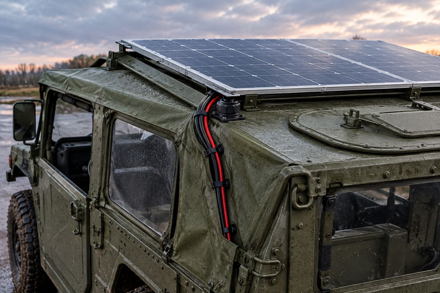
A roof rack can cast a narrow shadow across a panel. Check the proposed position with roof kit fitted, not with an empty rack that will later carry storage.
Expected result: the panel and battery are restrained, penetrations are sealed, and cables cannot rub, stretch or snag during normal vehicle movement.
Battery connection and controller configuration
- Isolate the sources. Keep the PV circuit disconnected or isolated using the specified equipment. Isolate alternator and external charging sources, and follow the vehicle's battery-disconnection procedure. Verify isolation before touching conductors.
- Install the protected battery circuit. Fit the controller's battery wiring with protection close to the battery on each conductor requiring it under the design. Leave the circuit isolated while terminating cables. Use correctly crimped terminals, terminal covers and specified tightening torques.
- Complete the return path. Follow the designed negative-return and chassis-bonding arrangement. Do not assume a body bolt is a suitable electrical connection. Where a battery-monitor shunt is fitted, route charging returns as its instructions require.
- Connect and configure the controller. Follow its prescribed connection order. Many controllers require the battery connection before PV; verify this in the actual manual. Set battery voltage, chemistry, charge limits and temperature controls using the manufacturer's exact instructions.
- Connect the PV circuit. Verify polarity and the permitted input voltage before energising it. Use compatible connector components and proper tooling. Never unplug ordinary PV connectors under load.
No universal menu label or terminal layout applies to every controller. Read the markings on the actual unit; do not copy another installation's settings because its battery looks similar.
Expected result: the controller recognises the intended battery system and shows no polarity, voltage or battery-profile fault before charging begins.
Load distribution and commissioning
- Keep loads on a protected distribution circuit. Feed habitation equipment through appropriately protected circuits. Do not put a large load on the controller's load terminals unless their manual explicitly permits that use.
- Check the charging path. With suitable daylight, confirm the controller reports charging and verify readings against the battery manufacturer's limits. A full battery can accept little current without indicating a fault.
- Test the intended loads. Check operation, voltage drop and connections under normal demand. Investigate abnormal heating, smells or unstable readings immediately; isolate the system rather than continuing the test.
- Prove the isolation scheme. Confirm which circuits remain live with the vehicle master switch off. Solar, auxiliary and alternator charging routes must behave as the drawing specifies.
- Document the installation. Label isolation points, battery chemistry, cable functions and fuse specifications. Save controller settings, manuals and the finished wiring drawing with the vehicle records.
For a 2026 installation, record the inspection date as well as the settings. That gives the next owner a clear distinction between the original vehicle loom and later additions.
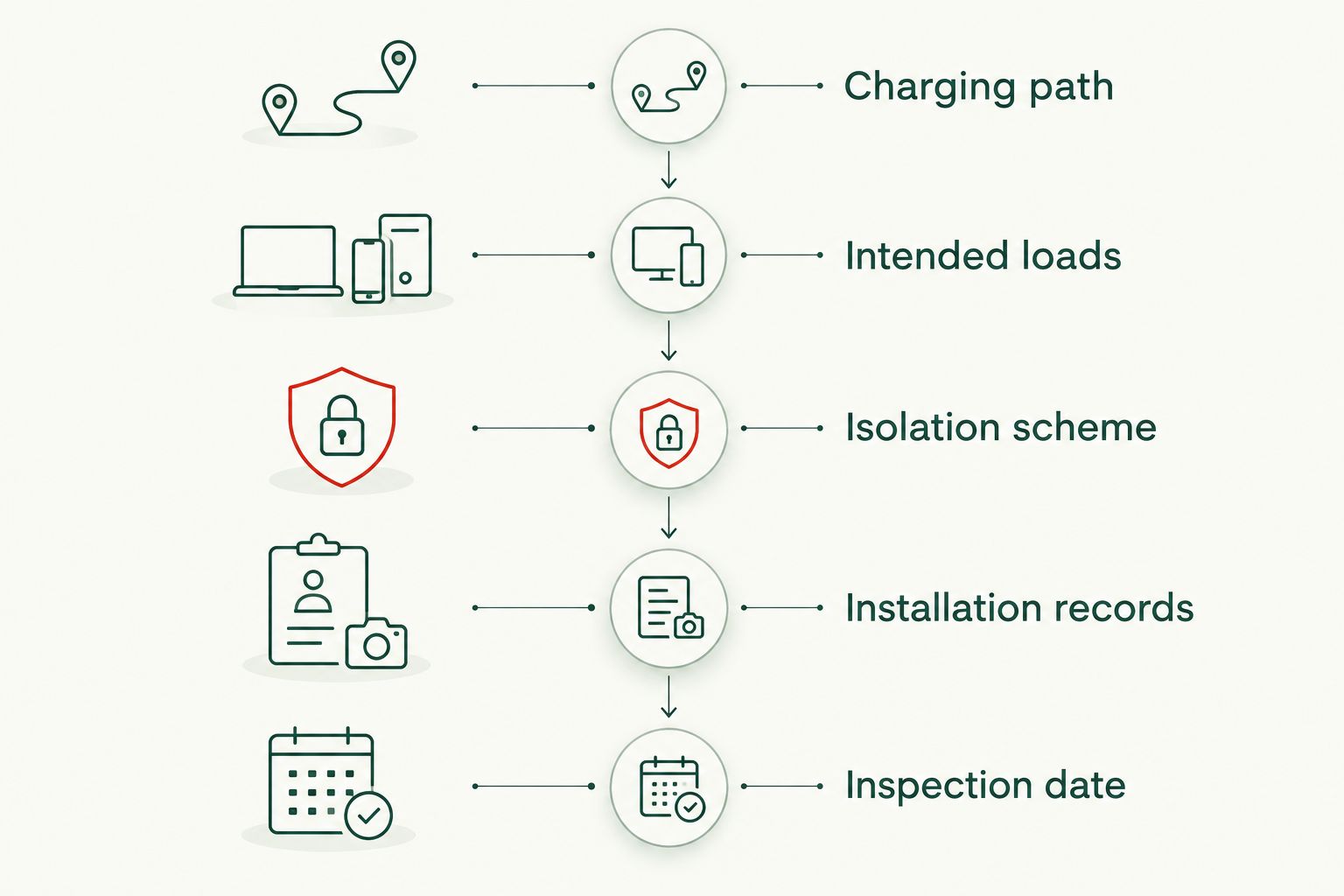
Expected result: charging, loads and isolation work as designed, with no unexplained heating or faults. Have the completed installation inspected before relying on it away from home.
How do you add charging while driving?
Solar charging and alternator charging can serve the same auxiliary battery when both chargers are compatible with that battery and with each other. Use a correctly specified DC–DC charger where the design requires controlled charging between the vehicle and habitation systems.
- Confirm the alternator system's voltage and operating characteristics.
- Select a DC–DC charger with the correct input range and auxiliary-battery charging profile.
- Follow its requirements for activation signals, cable sizing, isolation and protection at battery-connected sources.
- Commission the alternator route separately, then verify operation alongside solar charging and check combined current against battery limits.
A 24 V vehicle and a 12 V auxiliary battery require equipment explicitly designed for that conversion. Do not connect the battery banks directly or use an unspecified voltage reducer as a battery charger.
Expected result: the auxiliary battery charges with the engine running without an unintended discharge path from the starting bank when parked.
What should you check when solar charging fails?
- Controller is blank: check battery-side isolation, protective devices, battery voltage and polarity. Follow the controller's required start-up sequence. Do not assume a working panel will power an incorrectly connected controller.
- Charging current is low: check battery state, shading, panel cleanliness and controller status. Compare conditions and readings with the equipment instructions before blaming cable size or adding panels.
- Controller reports overvoltage: isolate PV using the specified procedure. Recheck series connections and cold-weather open-circuit voltage against the controller limit. Do not reconnect until the mismatch is resolved.
- A fuse blows or a terminal gets hot: stop and isolate. Inspect for shorts, damaged insulation, incorrect crimps, loose connections and unsuitable cable sizing. Never fit a larger fuse simply to stop it blowing.
- Charging stops in cold weather: check battery temperature and protection status. Lithium batteries need their specified low-temperature charging protection; never bypass a battery management system to force charging.
How should you customise the workflow?
Build around the kit you actually use. List each load's rated consumption and operating time, then size storage and charging around that demand. Roof space alone does not determine the right array.
For a 2026 upgrade, add monitoring before adding more panels. Battery and controller readings help distinguish excessive consumption from poor solar input. Keep any new accessory circuit separate from unidentified military wiring; the guide to wiring a dash cam into an ex-military vehicle covers an adjacent accessory project.
Military Mart's surplus range suits the wider vehicle and camping build. Select solar components by their electrical documentation, not by military appearance or a condition grade: used or NOS status does not establish compatibility.
FAQ
Can I wire a solar panel straight to an ex-military vehicle battery?
Use a compatible charge controller rather than connecting a bare panel directly to the battery. The controller must match the battery chemistry and voltage, with correctly designed cable protection.
Can a 24 V military vehicle have a 12 V leisure battery?
Yes, a separate 12 V auxiliary system can operate alongside a 24 V vehicle system. Any charging connection between them needs equipment explicitly designed for those input and output requirements.
Can I take power from just one battery in a series pair?
Do not use one battery in a series-connected starting bank as a lower-voltage accessory supply. Unequal loading unbalances the pair; use a separate auxiliary system or a properly designed conversion arrangement.
Should solar charge the starter battery or the leisure battery?
Charge the auxiliary battery for camping loads; use a compatible starting-bank arrangement for storage maintenance. These are different duties, and one does not automatically provide the other.
Does the vehicle battery isolator turn off the solar panels?
Not necessarily: an added solar circuit can remain live independently of the original vehicle isolator. Provide and label isolation according to the completed system design.
Will solar panels keep working in a British winter in 2026?
Solar panels generate in suitable daylight, but winter energy production is not a dependable substitute for an energy budget. Plan around seasonal conditions, shading, consumption and a suitable backup charging route.
Can I install the system myself?
Only undertake work you can design, isolate, terminate and test competently. Use an auto electrician for unidentified wiring, positive-earth systems, protection design or any uncertainty about safe commissioning.
One last thing
An engine-off vehicle is not necessarily an electrically isolated vehicle. Solar panels and an auxiliary battery add independent energy sources. For any 2026 conversion, a labelled isolation diagram is as important as the charging diagram: someone repairing the vehicle needs to know what remains live.


Leave a comment