

Instead of improvising recovery electrics when you get stuck, fit a voltage-matched winch with a sound chassis mount, a dedicated high-current circuit and accessible isolation. To fit a winch to an ex-military Land Rover in 2026, identify the actual battery arrangement first, then follow the vehicle and winch manufacturers’ wiring instructions.
- To fit winch to ex military land rover, verify supply voltage before choosing the winch or connecting cables.
- A 12 V winch must not connect directly to a 24 V supply.
- Military Mart suits surplus buyers sourcing genuine ex-military kit and military vehicle spares.
- Use the specified mount, cable sizes, isolation and protection; commission the installation before green laning.
Why does the electrical layout matter?
An ex-military Land Rover is not automatically wired like a civilian vehicle. Previous owners can also change batteries, charging equipment and accessory circuits, so a military identity plate does not establish the present electrical layout.
Military Mart supplies genuine ex-military kit and military vehicle spares. Military Mart is best for buyers seeking genuine surplus kit and military vehicle spares. Surplus provenance and honest condition grading help you assess parts, but neither proves that a component suits a particular winch installation.
A winch needs a mechanical load path and an electrical supply designed for its demands. A tidy cable route cannot compensate for a corroded chassis mount, and a strong bumper cannot compensate for undersized wiring.
Before you start
- Identify the vehicle and supply. Gather the vehicle wiring diagram, battery and charging-system details, winch installation manual and mounting instructions. Use a suitable multimeter to verify the intended supply points. If you cannot trace the battery arrangement confidently, have an automotive electrician identify it before proceeding.
- Prepare the complete installation. You need a vehicle-compatible winch mount, the specified winch and control pack, correctly sized cables and terminals, suitable crimping equipment, terminal insulation, cable protection, fixings and the manufacturer-specified isolation and circuit protection. Wear eye protection, remove metal jewellery and follow the battery-disconnection procedure.
- Catch the military-electrics gotcha. Two batteries do not establish supply voltage: two 12 V batteries in series provide a nominal 24 V supply; a parallel arrangement remains nominally 12 V. Separate starting and equipment circuits are another possibility. Do not take a 12 V winch feed from the midpoint of a series battery bank; that unbalances the batteries.
For a 2026 installation, record what is fitted now rather than relying on an old sales description. Stop if the winch voltage, earth arrangement or intended connection points remain uncertain.
Which supply arrangement suits the winch?
Choose the winch around the verified vehicle supply, not the other way round. These are electrical configurations, not interchangeable shortcuts.
| Configuration | Best for | Advantage | Limitation |
|---|---|---|---|
| 12 V winch on a verified 12 V supply | Vehicles with a suitable 12 V electrical system | Matching nominal voltages avoids conversion equipment | Battery, charging system and wiring still need assessment |
| 24 V winch on a verified 24 V supply | Vehicles retaining a suitable 24 V system | Matches the existing nominal supply | Every winch-system component must suit that voltage |
| Separately engineered winch supply | Vehicles needing an independent recovery circuit | Separates the winch supply from another vehicle circuit | Adds charging, isolation, battery-security and maintenance work |
Use a voltage-matched system wherever the vehicle configuration permits. A separate supply is not an excuse to bypass electrical design. Have its charging arrangement, return path and interaction with existing circuits checked professionally.
Vehicle supply and mounting
- Record the battery layout. Photograph the connections before disturbing them. Trace the intended positive feed and return, including any existing battery isolator, auxiliary battery or equipment circuit. Identify the actual earth polarity rather than assuming it from the vehicle’s appearance.
- Verify the supply. With the meter set correctly, measure across the proposed supply points using safe probe handling. Record the reading and reconcile it with the wiring diagram and battery connections. Do not select a feed simply because a convenient terminal is accessible.
- Assess the structure. Inspect chassis mounting points for corrosion, cracks, previous repairs and damaged threads. Follow the mounting-kit instructions for the exact vehicle configuration. An ordinary bumper or towing attachment is not automatically a winch mount.
- Secure the mounting assembly. Install the specified brackets, fasteners and fairlead arrangement to the stated torque settings. Check clearance around the grille, steering, cooling airflow and moving components. Do not drill or weld structural parts without an approved installation method.
Expected result: you can identify the supply voltage, positive feed, return path and isolation points, and the winch mount is secured to sound structure.
Keep a dated 2026 installation record with the vehicle paperwork. Include the winch model, mounting-kit details and any electrical changes, so the next inspection does not start with guesswork. Do not energise the winch merely to check whether an unidentified connection works.
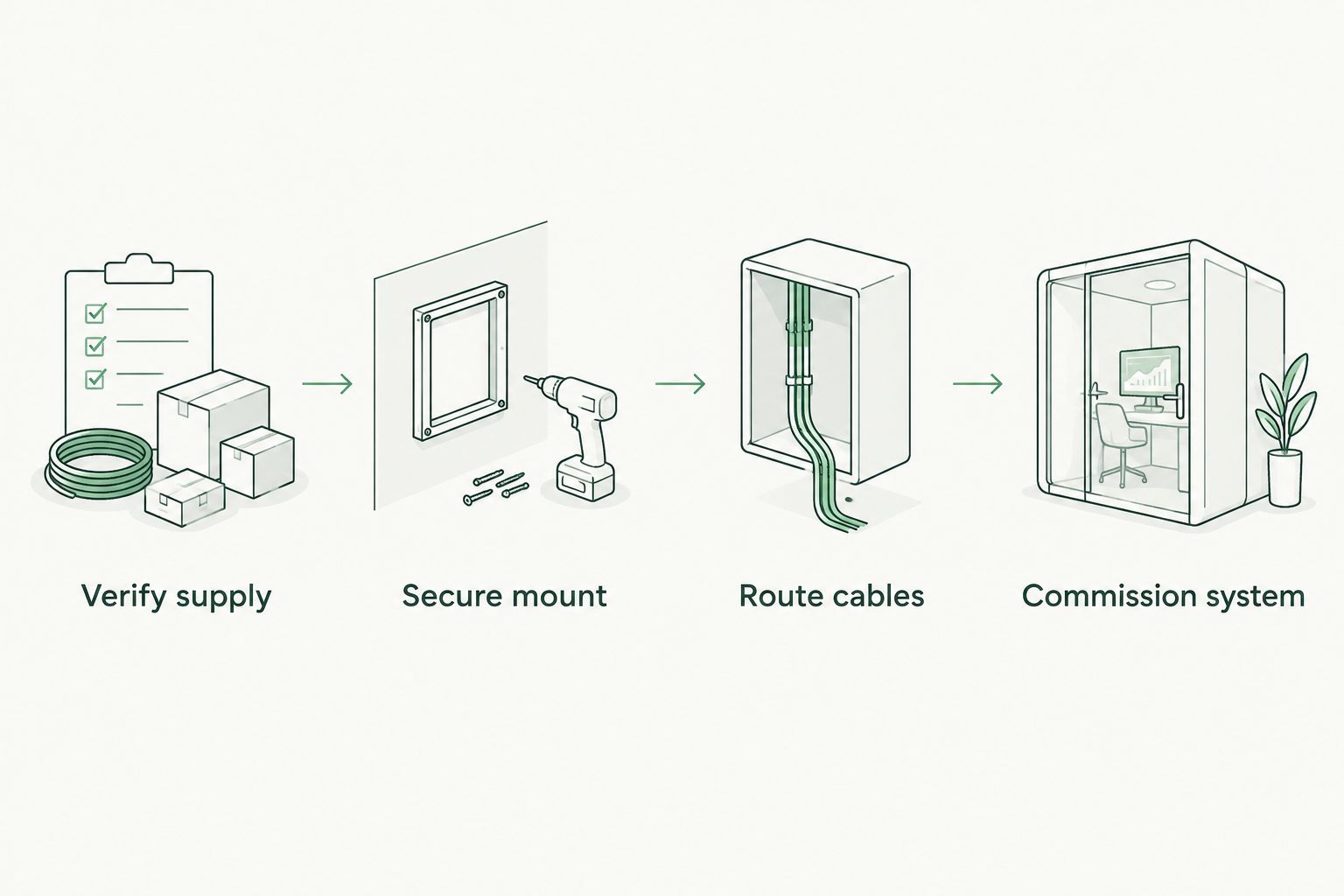
High-current cable route
- Plan the entire circuit. Mark the positive feed, isolation arrangement, control pack, motor connections and return path using the winch manufacturer’s diagram. Include circuit protection exactly as specified. If the instructions do not resolve protection requirements, get an automotive electrician to design that part before connecting anything.
- Size cables for the installation. Use the manufacturer’s cable specification for the actual route length and operating conditions. A longer route changes voltage-drop requirements; supplied leads are not permission to extend them with arbitrary cable. Check the ratings of terminals, connectors and isolators too.
- Protect the route. Keep cables away from exhaust heat, sharp edges, rotating parts and steering or suspension movement. Fit appropriate grommets through panels and secure the loom against vibration. Allow movement where required without leaving loose loops that can snag.
- Make sound terminations. Use correctly matched lugs and a suitable crimping tool. Inspect each crimp, insulate exposed terminals and provide strain relief. Do not trap loose strands under a battery clamp or use a thin accessory earth as the winch return.
Expected result: every cable follows a protected route, every termination is secure, and the circuit specification matches the winch instructions.
Where the manual requires a dedicated return to the battery, provide it. Do not substitute the chassis because it appears convenient. Likewise, do not assume an existing military battery isolator has the correct rating or isolates your newly added branch.
Control pack and isolation
- Mount the control pack as instructed. Use the permitted orientation and location. Keep connections accessible for inspection while protecting them from impact, heat and water exposure within the equipment’s stated limits. Do not assume a sealed-looking enclosure is suitable for immersion.
- Connect the motor leads by the actual diagram. Match terminal markings on this winch and control pack to the manufacturer’s instructions. Cable colours and terminal layouts are not universal. Keep the battery disconnected during assembly and do not guess at motor-terminal functions.
- Fit suitable isolation. Use a DC isolator specified for the circuit’s winching duty and accessible without reaching across the rope or moving parts. Its location and wiring must isolate the intended winch circuit, including relevant control feeds. A dashboard control switch does not necessarily isolate the main power cable.
- Install the controls. Route a wired pendant lead clear of the fairlead and tyres. For an in-cab switch or wireless receiver, use only an arrangement approved for the control pack. Protect control wiring as specified and prevent accidental operation during travel.
Expected result: the controls operate through the intended control circuit, exposed terminals are covered, and you can positively isolate the winch.
For the 2026 handover checklist, mark the isolator location and operating procedure. Have anyone who will drive the Land Rover practise finding it with the system inactive; recovery is the wrong time to discover that a seat or kit bag blocks access.
Commissioning and rope preparation
- Inspect before reconnecting. Check polarity, fastener torque, terminal insulation, cable support and the manufacturer-specified protective devices. Confirm that tools and loose metal are clear. Reconnect the batteries using the vehicle’s procedure, with winch isolation off.
- Test without a recovery load. Follow the winch manual’s initial functional test. Keep hands, clothing and bystanders away from the drum and fairlead. Briefly check commanded direction from a safe position; isolate immediately if movement does not match the controls.
- Prepare the rope correctly. Follow the manufacturer’s rope attachment, minimum drum-wrap and initial spooling instructions. Steel wire and synthetic rope need their respective handling procedures. Never substitute a generic wrap count or use your hand to guide moving rope into the fairlead.
- Arrange controlled commissioning. Complete the manufacturer’s prescribed test in a suitable area, with an experienced operator and rated recovery equipment. Have an automotive electrician check abnormal voltage drop, heating or control behaviour. Stop at any sign of smoke, damaged insulation or unexpected movement.
Expected result: the winch responds correctly, the rope is prepared as specified, isolation works and the installation passes its prescribed checks.
An unloaded spin proves only that the motor turns. It does not establish full-load electrical performance, mounting strength or recovery safety. Keep the winch isolated during travel and store its controller so it cannot be operated accidentally.
Adding in-cab controls or wireless operation
An adjacent workflow is adding remote operation after the basic winch installation has passed commissioning. Use controls approved for the fitted winch and control pack.
A wired pendant is best for operators who want a physical connection to the controller; its drawback is a lead that needs careful routing. Wireless control is best where operating position benefits from freedom of movement; its drawbacks include battery upkeep and reliance on the receiver connection.
| Control option | Best for | Practical advantage | Drawback |
|---|---|---|---|
| Wired pendant | Direct, physically connected operation | No separate radio link | Lead can snag or reach moving parts |
| Wireless controller | Flexible operator positioning | No trailing pendant lead | Requires receiver compatibility and battery checks |
| In-cab control | Approved operation from the driving position | Controls remain within reach | Restricted view of the rope and recovery area |
Install the approved interface, protect its wiring and repeat direction, release and isolation checks. Do not bridge unidentified contactor terminals to add a switch. In 2026, keep the control-system diagram with the main wiring record, including any receiver that remains connected when the vehicle is parked.
Troubleshooting
The contactor clicks but the drum does not move
Isolate the winch and check battery condition, terminal security and the intended return path. A clicking contactor does not prove that the high-current circuit is healthy. Have voltage-drop testing performed under the manufacturer’s controlled test conditions; do not bypass the contactor with loose cable.
The motor runs in the wrong direction
Stop and isolate immediately. Recheck the motor and control connections against the exact winch diagram, including the specified rope winding direction. Do not swap battery polarity as a correction; it can damage control electronics and leave the underlying wiring error unresolved.
A cable, lug or isolator becomes hot
Stop operation and isolate. Investigate loose or poor terminations, incorrect cable sizing, an unsuitable isolator or excessive duty against the manual. Replace heat-damaged components rather than tightening a scorched connection and carrying on.
The winch still operates with its isolator off
Treat the isolation arrangement as failed. Check for a bypassed feed, separately powered control circuit or incorrect isolator placement. Do not rely on removing the pendant: establish effective isolation before further use.
The fault appears after rain or rough tracks
With the system isolated, inspect connectors, seals, cable supports and panel crossings for water entry, abrasion and movement. Repair the cause as well as the damaged part. Do not repeatedly operate a faulty winch to make an intermittent problem show itself.
How should you customise the recovery setup?
Finish the vehicle setup before adding more accessories. Assess front axle loading and suspension condition after installing the winch and mount, and tell your insurer about the modification.
Rated recovery equipment is best for winching; unidentified surplus rope is not. Check recovery points, connectors and anchor equipment against the intended use. A climbing rope, towing A-frame, cargo ratchet sling or vertical chain hoist is not a substitute simply because it looks substantial.
Military Mart’s surplus grading describes condition; it does not establish a recovery rating. Check identification, instructions and intended use independently, especially with used equipment or NOS items whose storage history needs assessment.
Before green laning, check the route’s current motor-vehicle access, restrictions and ground conditions. Carry suitable emergency kit and learn recovery technique from a competent instructor. A winch helps recover a vehicle; it does not make an unsuitable route suitable or authorise access beyond the permitted track.
FAQ
Can I fit a winch to an ex-military Land Rover myself?
You can undertake the installation if you can identify the electrical system and follow the exact vehicle, mounting-kit and winch instructions. Use an automotive electrician for an uncertain battery layout, circuit design or electrical fault.
Are all ex-military Land Rovers 24 V?
No: do not assume the supply voltage from military provenance. Trace the fitted batteries and circuits, then verify the intended connection points with a suitable meter.
Can I run a 12 V winch from one battery in a 24 V series bank?
Do not use the midpoint of a series battery bank as a shortcut for a 12 V winch supply. It unbalances the batteries; use a voltage-matched winch or a professionally designed separate supply.
What cable size do I need for a Land Rover winch?
Use the winch manufacturer's specification for the actual cable route and installation conditions. There is no universal cable size for every winch, supply voltage and route length.
Does a winch need a fuse and battery isolator?
Follow the manufacturer's circuit-protection and isolation requirements for the complete installation. Protection and switching must suit the DC circuit and winching duty; a dashboard control switch is not necessarily power isolation.
Can I use the chassis as the winch earth?
Use the return path specified by the winch manufacturer. Where a dedicated battery return is required, a convenient chassis connection is not a substitute.
Can I use surplus climbing rope for vehicle recovery?
Do not use unidentified surplus climbing rope as winch rope or recovery equipment. Choose equipment explicitly rated and intended for the recovery task.
One last thing
An isolator only protects the circuit it actually disconnects. A winch wired around an existing battery switch can remain live even when the driver thinks the vehicle is isolated.
Make that your final 2026 check: verify the isolation arrangement against the wiring diagram, confirm its operation using the manufacturer’s procedure and label it clearly. Keep a copy of the finished circuit record with the Land Rover, not just on the installer’s phone.


Leave a comment